
|
|
|
Aligning
and Balancing the Model T Ford Engine and Transmission Updated
April 2008
The
basic design of the Model T Ford engine/transmission “demands” careful alignment
and balancing. Differing
from most others, the Model T Ford engine has an 85-pound rotating mass
transmission bolted on the rear of the crankshaft that must be aligned and
balanced. Since there are four
different ways the transmission may be assembled to the engine (both the
transmission main shaft and crankshaft flanges may be turned 180 degrees); any
time the Model T transmission is removed from the engine for maintenance, an
opportunity for misalignment is introduced.
Over the life of an engine, several such opportunities may have occurred
perhaps accumulating and resulting in severe misalignment.
Crankshaft regrinding, re-babbiting, parts used from other transmissions,
and/or assembly errors may unknowingly introduce misalignment.
For example, a rather common occurrence in the crank shaft re-grinding
process is grinding the main bearings off center from the alignment pins.
These problems must be resolved during engine/transmission reassembly
procedure. Also, a common practice
is to have one craftsman rebuild the transmission and another rebuild the engine
and the two simply bolted together upon return; completely skipping the
alignment process! Misalignment will
severely drain horsepower from the engine. We
only have 20 horsepower or so and we need all of it.
A
good foundation is required.
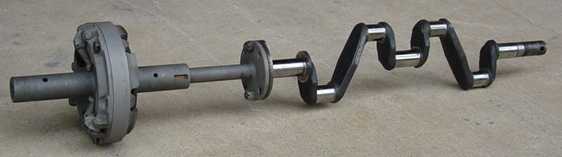
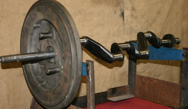
The photo above shows all the components that affect the alignment: crankshaft,
mainshaft, brake drum and drive plate/output shaft. The path to a correct running fit on the tail shaft starts with the
crankshaft. Concentricity must then
be maintained starting with the crankshaft and carried through the transmission
main shaft, flywheel, brake drum and sleeve and drive plate and sleeve (tail
shaft). The distance from the back
of the crankshaft flange to the rear-most tip of the tail shaft sleeve is
approximately 11½ inches; thus even a slight tilt or off-set will introduce a
wobble at the end of the tail shaft.
Crankshaft Grinding
The alignment procedure is greatly simplified if the crankshaft bearings are reground aligned with the alignment pins. Alignment
is Critical
– We believe it was Ford’s intention that the crankshaft crank pin bearings
and main bearings be ground at the factory aligned with the alignment pin holes
in the crankshaft flange. These
alignment pins have a snug fit in the crankshaft and the transmission main shaft
flanges and are a press fit into the flywheel, all well designed to carry an
accurate alignment to the rear. Indexing
a crankshaft grinder on the alignment pins requires a special fixture
– Crankshaft grinding machines have lathe chucks on either side, plus the
capability of using the lathe centers on either side.
For example, the front end of the Model T crank may be chucked on the
left side of the grinder, with the surface under the crank gear providing an
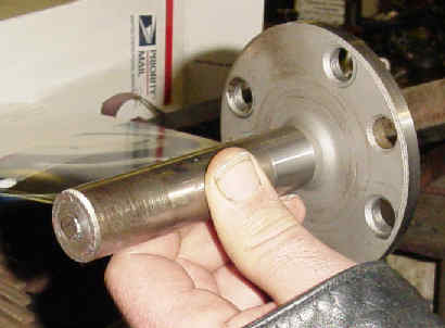
accurate attachment surface. Since all surfaces on the used flange end are
suspect, a fixture (see photo below) made from an extra transmission main shaft
will assure the bearings will be reground aligned with the alignment pins as the
factory originally intended.
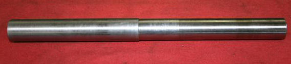
Making
the Fixture –
Select a transmission main shaft in nice condition and cut about 3 inches off
the shaft leaving the flange with about a 3 inch stub shaft.
Drill out and thread the four bolt
holes in the flange to ½ by 20.
Prepare four ½ by 20 thread bolts, short enough so they will not
protrude beyond the crankshaft inner flange surface when the fixture is attached
(this to allow grinding on the front surface of the crankshaft flange). Preparing
the crankshaft to be ground
– Bolt the fixture to the rear surface
of the crankshaft flange with the alignment pins inserted.
Next, the fixture shaft is chucked into the left 4 – jaw chuck and
centered by indexing on the shaft of the new fixture.
This procedure will provide a very accurately ground crankshaft…….UNLESS…the
crankshaft was not correctly ground at the factory (aligned with the alignment
pins). In this instance, if you
choose to use this crankshaft, the crankshaft may be ground aligned on the least
worn main bearing and the transmission alignment procedure (described below)
used to align the transmission, plus your crankshaft, transmission main shaft
and flywheel must be dynamically balanced as a unit.
Note: If you are grinding a Model A shaft to be installed in a Model T
block, the exact crankshaft grinding procedures would be used as the alignment
pins and bolt holes are essentially the same size and location, the only
difference being the Model T pin hole is push fit and the Model A is a press
fit. Also, if you are using the full
length rear main, the model A flange has 7/16 by 20 threaded bolt holes.
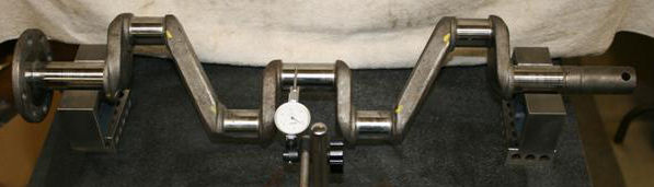
Alignment
tasks are accomplished by placing the engine block with the installed crankshaft
nose down on an engine stand. The
transmission is then assembled piece by piece onto the engine. This method
removes the gravity component from all measurements, plus all measurements are
made with a dial indicator mounted on the block allowing concentricity to be
measured by turning the engine and transmission components in exactly
the same manner as when the engine is running. Step
1
-
It is critical that the transmission
main shaft be aligned with the crankshaft main bearings to a high degree of
accuracy. Usually
the crankshaft is freshly
reground, but any time the engine is removed, alignment and balancing should be
considered. Remove the crankshaft
from the engine and use V blocks with a surface plate and dial indicator to
check if the crankshaft is straight.
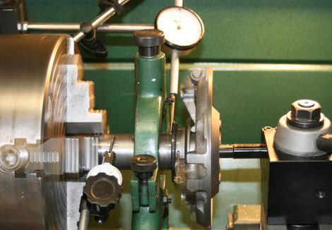
Prepare
the transmission main shaft. Center the transmission main shaft in the four-jaw
chuck using a light half-inch grip along with the steady rest.
True the outer flange surface to remove “cupping” on this surface.
Note: All outer flange
surfaces of transmission main shafts we have checked to date have been cupped,
that is, the outer edge of the flange surface is higher than the center.
This “cup” must be removed to allow an accurate fit to the crankshaft
flange (see left photo below). As
with the crankshaft, turn .008” from the
circumference of the main shaft flange (right photo below).
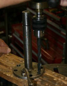
Then, as shown in the photo at left, use the drill press to bore the main shaft alignment pin holes with a 31/64” drill bit (increasing the diameter of the hole from 15/32” to 31/64” or 1/64”). Caution, relieve only the main shaft alignment pin holes. This allows movement of the main shaft in the alignment process.
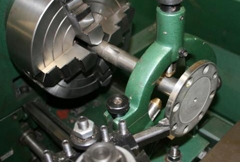
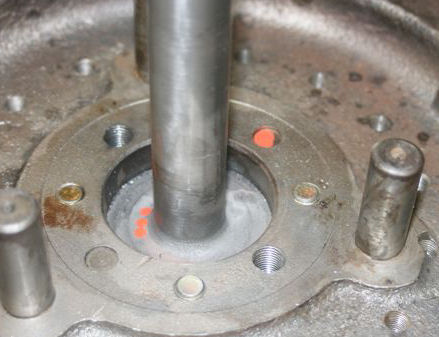
Trial
fit the transmission main shaft to the crankshaft –Begin
by carefully cleaning and oiling all the main bearing surfaces on the crankshaft
and block. Next, snug fit the crankshaft in the
block so the crank may be turned easily by hand. With the engine block nose down
on the engine stand, trial fit the transmission main shaft flange to the
crankshaft flange using bolts, nuts and loose alignment pins (photo at right).
Carefully center the main shaft to the crankshaft to within .0005” at
the top and bottom of the large bearing surfaces.
After achieving acceptable run out, tighten the nuts and bolts and verify
that the run out does not change. This
step is to verify the run out without the flywheel, and the same tolerance will
be duplicated in the next step when the flywheel is added to the mix.
Mark the main shaft and crankshaft for proper orientation and then
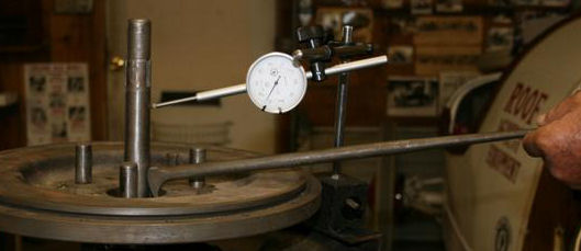
disassemble. Add
the flywheel to the properly oriented crankshaft/main shaft assembly. With the engine nose down on the engine stand,
place the dial indicator’s magnetic base on a short piece of angle iron or
square tubing bolted to the top block surface (see photo below left).
Install the flywheel and main shaft using four 7/16-20-grade 8 bolts 1
1/4 inches in length. At this time,
you may prepare six of these bolts by cross drilling the heads for safety wire
as used on the original bolts. The
extra two bolts will be used to pin
the main shaft in place after alignment to center.
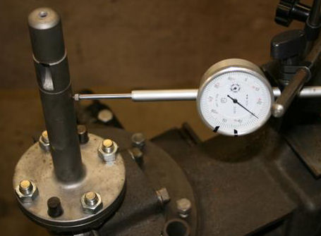
Install the crankshaft flange bolts and tighten just snug. Using the dial
indicator on the block and turning the flywheel, main shaft dial indicator
readings are taken near the top of the upper large diameter bushing area and
near the bottom of the lower bushing area (not on the bearing surface of drive
plate bushing). The goal here is to
center align the main shaft perfectly straight with dial indicator readings to
within .0005” at the upper and lower large diameter bushings areas.
Only the main shaft will be moved. The
original alignment pins remain pressed into the flywheel and passing through the
main shaft flange to a snug fit in the crankshaft flange to preserve the
integrity of the crankshaft to flywheel fit.
These unique pins are three-diameter with the larger diameter in middle
(main shaft flange). Only the main
shaft flange alignment pin holes have been relieved 1/64” to allow movement
for centering. Since the crankshaft
bolts are just snug, the main shaft may be gently moved to center with a small
pry bar (between the main shaft and flywheel) while turning the flywheel and
observing the readings on the dial indicator. Once
the main shaft is centered, the bolts should be tightened while observing the
dial indicator reading and always tightening the bolt with the lowest reading. DO
NOT PROCEED UNTIL THE SHAFT IS STRAIGHT
AND CENTERED TO WITHIN .0005”. Note
– If you are unable to achieve the same reading as the previous trial fit
without the flywheel, then the flywheel is the culprit.
First, make sure the alignment pins are completely seated in the
flywheel. Next, try bumping the
flywheel in the direction needed with a small block of wood and a hammer.
Then, use a feeler gauge to check for flange perimeter interference with
the flywheel on both the transmission main shaft and the crankshaft flanges.
If necessary, disassemble and turn the flange circumferences as nee Lock the transmission main shaft in the aligned location. To lock the main shaft in the newly centered location, two holes are drilled from the top at 90 degrees from the original alignment pins, and then the holes are threaded 7/16-20. The placement of these two extra holes is not critical and an obvious offset will force a correct re-assembly at some later date. Two of the previously prepared 7/16” grade 8 bolts are now installed in these threaded holes. Thus the next person who opens this engine will simply see six crankshaft bolts rather than the normal four. Note: Some have suggested that alignment be achieved by replacing the original alignment pins with new bolts or pins. We prefer to maintain the integrity of the original alignment of the flywheel with the crankshaft and move only the main shaft. Our reasoning is that we want to retain to the greatest extent possible, the original engineering and alignment afforded by the complex, original three-diameter alignment pins. Step 2 - Balancing the crankshaft/flywheel Assembly - Remove the crankshaft/main shaft/flywheel Step 3 – Centering the brake drum and sleeve and
the drive plate and sleeve assembly - Remove
the bushing and soft plug from drive plate sleeve and the two bushings from the
brake drum sleeve. We have
determined that Ford was not too concerned with the accuracy of the internal
bore of these sleeves, apparently relying on the accuracy of the final bore of
the bronze bushings. Thus, our
procedure does the same. We have made a special run of the brake drum sleeve
bushings (two each required) and the drive plate sleeve bushing (one each).
These bushings are the same outside diameter and length as the original
bushings but leaving .010” additional material inside to bore accurate holes
inside. These bushings also have the
internal oil grooves, which are the same as the originals.
Press these bushings into the brake drum sleeve and the drive plate
sleeve. Don’t forget that the
brake drum sleeve bushing which meets the transmission main shaft flange must be
pressed about 3/8” deep because of the main shaft radius. First,
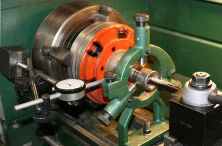
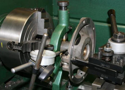
chuck the brake drum surface in an independent four-jaw chuck.
Index the sleeve near the drum and below the key slots to within
.0005”. zero run out is ideal, but the wear of the sleeve makes this difficult
to attain. We use a steady rest to
support the sleeve during the boring process (see left photo below). Bore bushings to
.996”. Remove the brake drum and
use the four-jaw clamp on the surface of the sleeve in the key area. Using the
steady rest index the sleeve as before and take a truing cut on the bolt-hole
flange surface (right photo below). (Note: we have found
that the bolt flange surfaces of both the brake drum and drive plate to have run
out.)
Place
the drive plate in the lathe with the sleeve in the four-jaw clamp on the first
½” or so. Using a steady rest, index on both ends of the sleeve with the dial
indicator. An old shifter
collar with a set screw in the center may be used to hold the clutch fingers in
place. Bore the bushing to .933”
(left photo below) and then true the flange bolt surface (right photo below).
The
early type requires the bolt hole flange to be trued and the lip should be
cleaned the same amount that was removed from the flange surface.
Failure to do so will not allow the flange surface to make full contact
with the brake drum (not necessary on 26/27 models).
This
mandrel is used as a center for the final bolt pattern fit between the brake
drum and the drive plate. Place the
mandrel on centers in the lathe with the brake drum on the left and the drive
plate on the right (left photo below), bolt surfaces together in center.
Using dial indicators, on the sleeve surfaces,
do
a trial fit of all six bolt positions to find a position that (a) does not lock
up on the bushing, and (b) has the least run out on the tail shaft sleeve.
Note: it appears that some run out to .001” will not cause any problems
here. Install and tighten all
fasteners. Do
not take apart until the following procedures are completed.
It
is now time to turn the tail shaft to the final fit of the 4th main
bearing (right photo above). A steady rest should be
used to better support the tail shaft for turning.
Either the four-jaw or a lathe dog may be used to turn the assembly.
Whether using babbitt or ball type 4th main bearing, turning
may or may not be required. Some ball bearing types require turning the drive
plate down to 1½” outside diameter. After
your decision as to the 4th main configuration, the drive plate/brake
drum assembly may be removed from the lathe and remove the mandrel from the
assembly.
Finally,
a standard Model T Ford 1” tapered reamer is used to ream the brake drum
bushings (Note: ream to fit transmission main shaft).
Check
the final results by cleaning, oiling and assembling to the transmission main
shaft. Our final run out result at
the tail shaft has been found to be something in the .004” to .006” range.
Remember, we have bearing clearance on all three main shaft bushings;
therefore, there will be run out. If
your readings are outside this range, carefully review all the above procedures.
The brake drum and drive
plate may now be separated. Next,
static balance, on knife edges, the brake drum, drive plate, low and reverse
drums. Refer to the MTFCA
transmission manual.
Carefully
clean, oil and reassemble the completed engine.
Don’t forget to install the soft plug in the tail shaft sealed with a
liberal amount of RTV. Complete the
assembly of the transmission and install engine pan and transmission cover.
Final fit the 4th main bearing by bumping (bending the pan)
with a block of wood and small sledgehammer until the 4th main slips
easily into place. On the 26/27
models, alignment can usually be achieved by adjusting the shims between the
hogshead and block. Addendum:
Fellow Model T Ford engine re-builders; these procedures are not chiseled
in stone; they represent our best efforts to date.
We have about 8 engines in the field using these procedures.
These procedures are difficult; and, require a lathe and a fairly
sophisticated machinist. We want
these procedures to continue to evolve; to simplify, and improve the accuracy;
and we need your input to make that happen.
If you have an idea how to improve these procedures in any way, please
share your ideas with Mike Bender at tman1913@sbcglobal.net
or Fred Houston at modeltgrg@cox.net . We are now able to perform this procedure in 4 to 6 hours depending on the condition of the transmission.
|
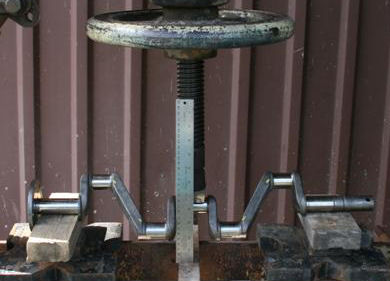 The crankshaft may be straightened on a press
protected by wood blocks on both top and bottom. A bent crank shaft will have a
flange that is not perpendicular to the crankshaft main bearings (tilted).
The crankshaft may be straightened on a press
protected by wood blocks on both top and bottom. A bent crank shaft will have a
flange that is not perpendicular to the crankshaft main bearings (tilted).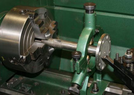

 Our
next step is to bolt the brake drum to the drive plate using a mandrel.
Our
next step is to bolt the brake drum to the drive plate using a mandrel.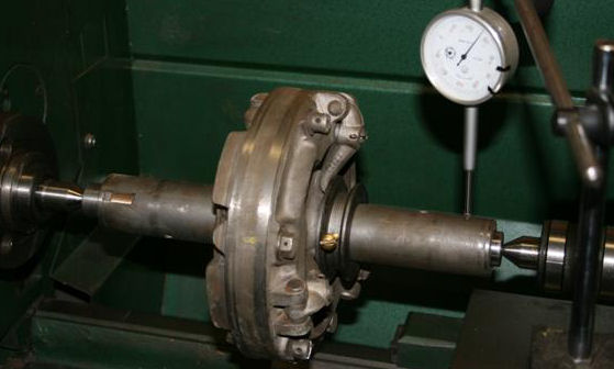
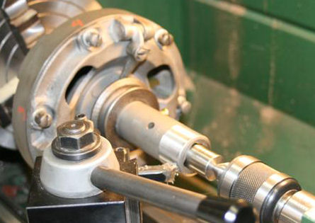
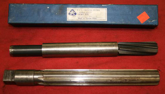 Reamers
are now used to make the final fit of the brake drum and drive plate bushings on
the transmission main shaft.
Reamers
are now used to make the final fit of the brake drum and drive plate bushings on
the transmission main shaft.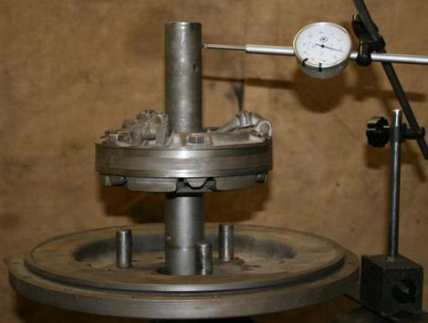 We
need to address “total” run out.
We
need to address “total” run out.